Solved[December 2023] BCS41 - Fundamental of Comptuer Networks | IV SEM BCA IGNOU
Hey there! Welcome to KnowledgeKnot! Don't forget to share this with your friends and revisit often. Your support motivates us to create more content in the future. Thanks for being awesome!
1. (a) Differentiate between private key and public key cryptography. Give suitable example of each. (6 marks)
Answer:
Private key cryptography, also known as symmetric encryption, uses a single key for both encryption and decryption. This key must be kept secret and shared securely between the communicating parties. For example, the Advanced Encryption Standard (AES) is a widely used symmetric encryption algorithm. In practice, if Alice wants to send a secure message to Bob, they both use the same secret key. Alice encrypts the message with this key, and Bob decrypts it using the same key.
The main advantages of private key cryptography are its faster encryption and decryption processes, making it suitable for encrypting large amounts of data. However, the key distribution process is challenging because the secret key must be securely shared between parties. If the key is compromised, both the encryption and decryption processes are no longer secure.
On the other hand, public key cryptography, also known as asymmetric encryption, uses a pair of keys: a public key and a private key. The public key is used for encryption, and the corresponding private key is used for decryption. The public key can be openly shared, while the private key must be kept confidential. An example of public key cryptography is the RSA algorithm. In this case, if Alice wants to send a secure message to Bob, she encrypts the message using Bob's public key. Bob then decrypts the message using his private key.
The primary advantage of public key cryptography is that it simplifies key distribution, as the public key can be freely shared. This method also enhances security for key exchange and digital signatures. However, it is generally slower than symmetric encryption and less efficient for encrypting large amounts of data.
1. (b) Briefly discuss the concept of frequency shift keying and phase shift keying. Give an application of each. (6 marks)
Answer:
Frequency Shift Keying (FSK) is a digital modulation technique where the frequency of the carrier signal is varied according to the digital signal changes. In FSK, different frequencies represent different binary states (0s and 1s). For example, a higher frequency might represent a binary 1, and a lower frequency might represent a binary 0.
An application of FSK is in modems, which use this technique to transmit data over telephone lines. FSK is also commonly used in radio transmission systems where reliable data communication is necessary.
Phase Shift Keying (PSK) is another digital modulation technique where the phase of the carrier signal is varied according to the digital signal. In PSK, different phases represent different binary states. For example, in Binary Phase Shift Keying (BPSK), a 0 might be represented by a 0-degree phase shift, and a 1 might be represented by a 180-degree phase shift.
An application of PSK is in Wi-Fi communication, where it is used in various standards such as IEEE 802.11 to efficiently transmit data over wireless networks. PSK is favored in environments with high noise levels because it is less susceptible to errors.
1. (c) What is count to infinity problem in distance vector routing protocol? How does it happen? Explain with an example. (10 marks)
Answer:
The count to infinity problem is an issue in distance vector routing protocols where routers continuously increment the distance metric to a destination that has become unreachable, eventually reaching a very large value, often considered as infinity.
This problem occurs due to the lack of immediate awareness of network topology changes in distance vector routing. When a route to a destination becomes unavailable, routers increment their distance metrics in steps, based on their neighbors' updates, leading to a slow convergence to the correct route or recognition that the destination is unreachable.
Example: Consider three routers, A, B, and C, connected in a linear topology with initial distance metrics:
- A to B: 1 hop
- B to C: 1 hop
- A to C: 2 hops (via B)
If the link between B and C fails, B recognizes that C is unreachable and sets its distance to C as infinity. However, A, unaware of the failure, continues to believe it can reach C via B with a distance of 2. A updates its routing table and informs B, prompting B to believe it can reach C via A with a distance of 3, and this cycle continues, increasing the metric incrementally.
This cycle results in the count to infinity problem, where routers repeatedly increase the hop count until it reaches an upper limit defined as infinity, causing slow convergence and potential routing loops.
1. (d) Briefly discuss the functions of Layer-2 switch and Layer-3 switch. Compare Switch with Hub. (6 marks)
Answer:
A Layer-2 switch operates at the Data Link Layer (Layer 2) of the OSI model. It uses MAC addresses to forward data frames to the correct destination within a local area network (LAN). The primary function of a Layer-2 switch is to reduce collisions and improve the efficiency of data transfer by creating separate collision domains for each connected device.
A Layer-3 switch, on the other hand, operates at both the Data Link Layer (Layer 2) and the Network Layer (Layer 3). It performs routing functions similar to a router, using IP addresses to forward packets between different networks or subnets. Layer-3 switches are used to route traffic within larger, more complex networks.
Comparison with Hub:
- A hub is a basic networking device that operates at the Physical Layer (Layer 1) of the OSI model. It broadcasts incoming data to all ports, regardless of the destination, leading to more collisions and inefficient use of bandwidth.
- A switch, whether Layer-2 or Layer-3, forwards data only to the specific port associated with the destination device, reducing collisions and improving network performance.
1. (e) How does pure ALOHA differ from slotted ALOHA? Explain. (6 marks)
Answer:
Pure ALOHA is a simple communication protocol in which a user can send data at any time without checking whether the channel is free. If a collision occurs, the sender waits a random amount of time before attempting to retransmit the data. This approach can lead to high collision rates, reducing the overall efficiency of the network.
Slotted ALOHA improves on Pure ALOHA by dividing time into discrete slots. Users can only send data at the beginning of a time slot, which reduces the chances of collisions because transmissions are synchronized to the slots. If a collision occurs, the sender waits a random number of slots before retransmitting. This method roughly doubles the efficiency compared to Pure ALOHA.
In summary, while Pure ALOHA allows transmission at any time, leading to higher collision rates, Slotted ALOHA reduces collisions by requiring transmissions to start at specific time intervals, thus improving network efficiency.
1. (f) What are virtual circuits? Discuss the effect of router failure in virtual circuits. (6 marks)
Answer:
Virtual circuits are a method of data communication in which a pre-established path is created between the sender and the receiver before data transfer begins. This path appears as a dedicated physical circuit but is actually a logical path that shares network resources with other virtual circuits.
Effect of Router Failure:
- If a router along the virtual circuit path fails, the pre-established path is broken, leading to a disruption in the communication. Data packets may be lost or delayed until a new path is established.
- Depending on the protocol used, the network may attempt to reroute the traffic through an alternative path, but this can introduce additional latency and complexity.
- In some cases, the virtual circuit may need to be re-established entirely, causing a temporary interruption in the service.
2. (a) Differentiate between ARP and RARP. Explain the working of ARP using a diagram. (10 marks)
Answer:
ARP (Address Resolution Protocol) and RARP (Reverse Address Resolution Protocol) are both protocols used in computer networks to map network layer addresses (IP addresses) to data link layer addresses (MAC addresses) and vice versa. Here's how they differ:
- ARP: ARP resolves IP addresses to MAC addresses. When a device wants to communicate with another device on the same local network, it uses ARP to find the MAC address corresponding to the IP address of the destination device.
- RARP: RARP performs the reverse operation of ARP. It resolves MAC addresses to IP addresses. RARP is mainly used in diskless workstations to obtain their IP addresses from a RARP server.
Working of ARP: ARP operates on the principle of broadcasting. When a device needs to find the MAC address corresponding to a given IP address, it broadcasts an ARP request packet containing the IP address it wants to resolve. All devices on the local network receive this request, but only the device with the matching IP address responds with its MAC address. The requesting device then caches this mapping for future use.
Diagram: Below is a simplified diagram illustrating the working of ARP:
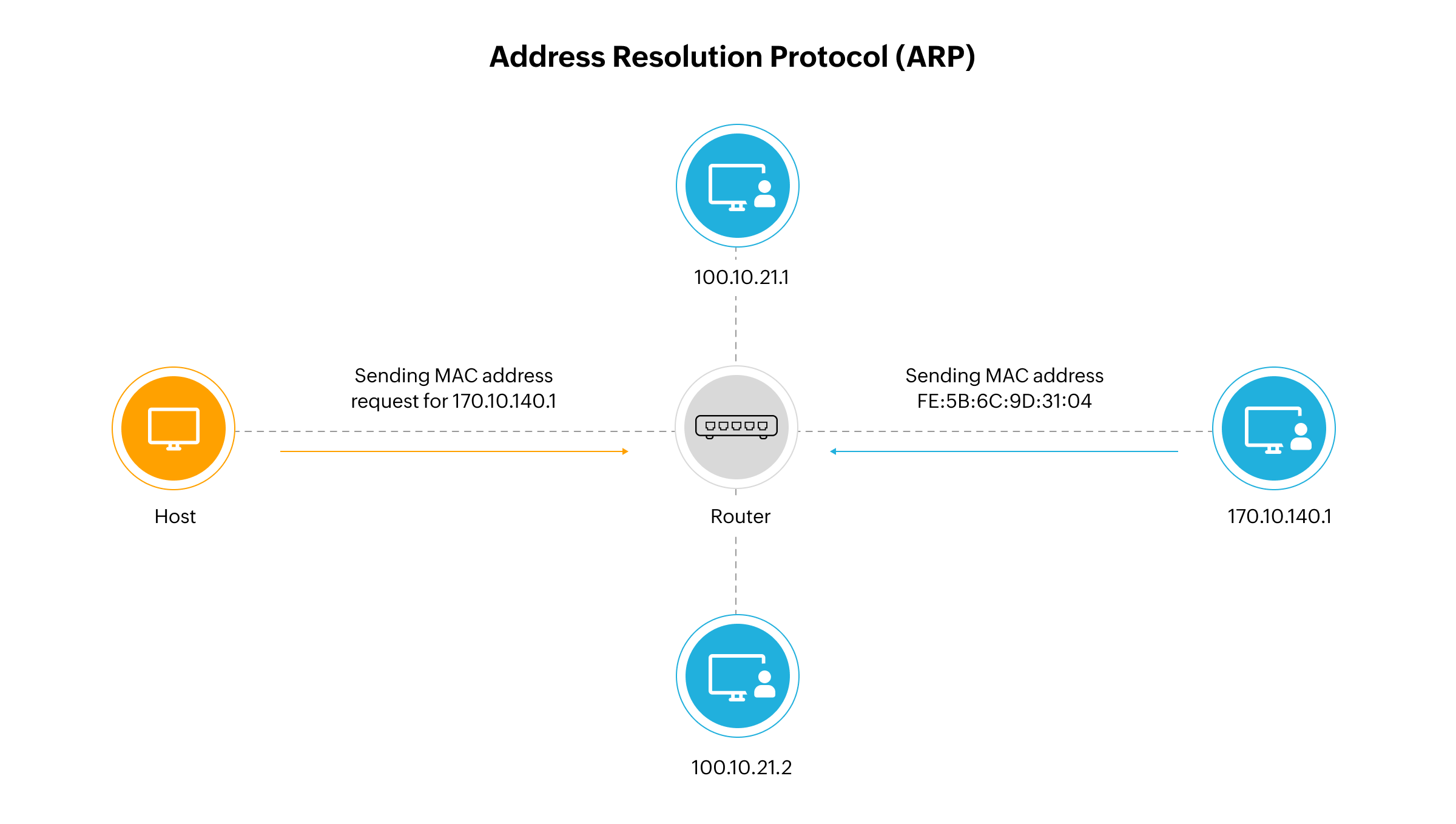
In the diagram:
- Device A wants to send data to Device B but does not know Device B's MAC address.
- Device A broadcasts an ARP request packet containing Device B's IP address.
- Device B, recognizing its IP address in the ARP request, responds with its MAC address.
- Device A receives Device B's MAC address and can now send data directly to Device B.
2. (b) How does classful addressing differ from classless addressing? How does classless addressing result in a decrease in the table size? (10 marks)
Answer:
Classful addressing and classless addressing are two distinct methods of IP address allocation, each with its own characteristics and implications for network management. Understanding the differences between these two addressing schemes is crucial for designing and managing modern networks effectively.
Classful addressing, which was the original method of IP address allocation, divides IP addresses into three main classes: Class A, Class B, and Class C. Each class has a fixed range of IP addresses and a predetermined subnet mask based on the class. For example, Class A addresses have a subnet mask of 255.0.0.0, Class B addresses have a subnet mask of 255.255.0.0, and Class C addresses have a subnet mask of 255.255.255.0. Classful addressing relies on these fixed boundaries to allocate IP addresses, which can lead to inefficient use of address space.
In contrast, classless addressing, also known as Classless Inter-Domain Routing (CIDR), eliminates the rigid class boundaries of classful addressing. With classless addressing, IP addresses are not restricted to predefined classes, and the subnet mask can be varied to create smaller subnets within a given address range. This flexibility allows for more efficient allocation of IP addresses and reduces address space wastage. For example, instead of allocating a whole Class C network (which contains 256 addresses) for a small organization needing only a few IP addresses, classless addressing allows for the allocation of a smaller subnet within a Class C network, conserving address space.
One significant advantage of classless addressing is its impact on routing table size. In classful addressing, routing tables need to store information about individual classful networks, which can lead to larger table sizes. This is because each classful network has its own entry in the routing table, regardless of its actual size or utilization. However, classless addressing allows multiple smaller networks to be summarized into a single, larger network block through route aggregation. Route aggregation reduces the number of entries in the routing table, thereby decreasing its size and improving routing efficiency. With classless addressing, routing tables only need to store information about the specific subnets that are being used, rather than every possible classful network.
In summary, classless addressing offers greater flexibility and efficiency compared to classful addressing. By eliminating the rigid class boundaries and allowing for variable-length subnets, classless addressing enables more efficient allocation of IP addresses and reduces address space wastage. Additionally, classless addressing results in a decrease in the size of routing tables due to route aggregation, improving routing efficiency in large-scale networks.
3. (a) Explain the concept Go-Back-N sliding window protocol with a suitable example and diagram. (10 marks)
Answer:
The Go-Back-N sliding window protocol is a reliable data transmission protocol used in network communication. It allows the sender to transmit multiple frames before receiving an acknowledgment from the receiver. Here's how it works:
Example: Consider a scenario where the sender (S) wants to transmit data to the receiver (R) over a reliable channel. The sender and receiver both maintain a sliding window of size N. The sender sends N frames (F0, F1, F2, ..., FN-1) sequentially to the receiver without waiting for acknowledgments.
Diagram: Below is a simplified diagram illustrating the Go-Back-N sliding window protocol:
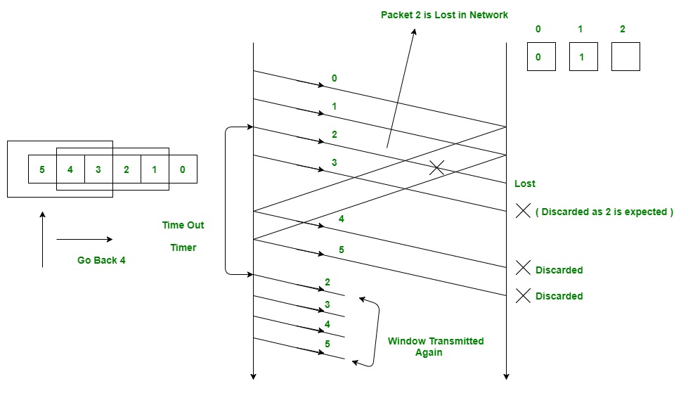
In the diagram:
- The sender (S) sends N frames (F0, F1, F2, ..., FN-1) sequentially to the receiver (R) without waiting for acknowledgments.
- The receiver (R) acknowledges correctly received frames by sending an acknowledgment (ACK) with the sequence number of the next expected frame.
- If the sender (S) receives an acknowledgment (ACK) for frame Fi, it moves the window forward to include the next frame (Fi+1) and continues transmission.
- If the sender (S) does not receive an acknowledgment (ACK) for frame Fi within a certain timeout period, it assumes that the frame was lost and retransmits all frames in the current window starting from Fi.
The Go-Back-N protocol offers advantages such as increased throughput and reduced overhead compared to other protocols like Stop-and-Wait. However, it has limitations, such as the potential for retransmitting unnecessary frames and increased complexity in handling out-of-sequence frames.
3. (b) What is Fragmentation? Explain why IPv4 and IPv6 protocols need to fragment some packets. (10 marks)
Answer:
Fragmentation is the process of dividing a large packet into smaller fragments to fit within the maximum transmission unit (MTU) size of a network. This process is essential for ensuring that data packets can traverse networks with varying MTU sizes without loss of data or degradation in performance.
In IPv4, the maximum packet size is limited to 65,535 bytes, including the header and data. However, different network segments may have different MTU sizes due to factors such as network technology, bandwidth constraints, or administrative configurations. When a packet's size exceeds the MTU of a network segment, it must be fragmented into smaller fragments to accommodate the smaller MTU size of that segment. IPv4 routers along the packet's path are responsible for fragmenting and reassembling packets as necessary to ensure successful delivery.
Similarly, IPv6 also requires fragmentation in certain scenarios. While IPv6 allows for much larger packet sizes compared to IPv4, fragmentation may still occur if a packet needs to traverse network segments with smaller MTUs. IPv6 routers are expected to perform path MTU discovery to determine the optimal MTU size for transmission, but fragmentation may still be necessary in cases where the packet size exceeds the determined MTU size.
Fragmentation adds overhead to network communication and can impact performance. Each fragment requires additional header information to indicate its position in the original packet, leading to increased overhead and bandwidth consumption. Additionally, fragmented packets may experience higher latency and increased susceptibility to packet loss, particularly in congested or high-latency networks.
While fragmentation is a necessary feature of network protocols like IPv4 and IPv6, efforts should be made to minimize fragmentation whenever possible. Path MTU discovery mechanisms help mitigate the need for fragmentation by determining the optimal MTU size for transmission, thereby reducing the occurrence of fragmentation and improving overall network efficiency.
In conclusion, fragmentation is a crucial aspect of network communication that enables data packets to traverse networks with varying MTU sizes. Both IPv4 and IPv6 protocols require fragmentation to ensure reliable data transmission, but efforts should be made to minimize fragmentation to optimize network performance and efficiency.
4. (a) Write the step-by-step working of link state routing. Also, compare it with distance vector routing. (10 marks)
Answer:
Link state routing is a routing algorithm used in computer networks to determine the shortest path between nodes. It operates by constructing a complete topological map of the network and then calculating the shortest paths based on this map. The following is a step-by-step explanation of how link state routing works:
- Topology Discovery: Each router in the network discovers its neighbors and the cost to reach each neighbor by exchanging link state packets. These packets contain information about the router's directly connected links.
- Database Creation: Each router constructs a database of the network topology using the received link state packets. This database includes information about all routers in the network and their connections.
- Shortest Path Calculation: Using the information from the database, each router calculates the shortest path to every other router in the network. This is typically done using Dijkstra's algorithm.
- Routing Table Generation: Based on the calculated shortest paths, each router generates its routing table, which contains the next-hop information for reaching each destination in the network.
- Packet Forwarding: When a router receives a packet, it forwards the packet to the next-hop router specified in its routing table until the packet reaches its destination.
Comparison with Distance Vector Routing: Link state routing differs from distance vector routing in several ways:
- Algorithm: Link state routing uses Dijkstra's algorithm to calculate the shortest paths, while distance vector routing uses the Bellman-Ford algorithm.
- Routing Updates: In link state routing, routers periodically exchange link state packets containing information about their directly connected links. In contrast, distance vector routing routers exchange routing tables with their neighbors.
- Convergence Time: Link state routing typically converges faster than distance vector routing because routers have a complete view of the network topology and can calculate shortest paths more efficiently.
- Scalability: Link state routing scales better than distance vector routing for large networks because routers only need to maintain information about their immediate neighbors rather than the entire network.
- Memory and CPU Usage: Distance vector routing requires more memory and CPU resources compared to link state routing because routers need to store and process complete routing tables.
In summary, link state routing constructs a complete topological map of the network and calculates the shortest paths based on this map, resulting in faster convergence and better scalability compared to distance vector routing.
4. (b) Discuss the concept of sliding window protocol with the help of an example. Also, explain how piggybacking technique works. (10 marks)
Answer:
The sliding window protocol is a method used in computer networks for reliable and efficient data transmission between two entities, typically a sender and a receiver. It allows multiple frames to be transmitted and acknowledged simultaneously, improving network throughput and efficiency. Here's how the sliding window protocol works with an example:
Example: Consider a scenario where a sender (S) wants to transmit data to a receiver (R) over a network connection. Both the sender and receiver maintain a sliding window of size N. The sender divides the data into fixed-size frames and transmits them to the receiver sequentially. The receiver acknowledges each frame as it is received and notifies the sender of any missing or out-of-order frames.
The sliding window protocol operates as follows:
- Frame Transmission: The sender transmits N frames to the receiver without waiting for acknowledgments.
- Acknowledgment: The receiver acknowledges correctly received frames by sending acknowledgment (ACK) packets back to the sender. The ACK packets contain information about the sequence number of the next expected frame.
- Window Sliding: Upon receiving an ACK for a frame, the sender slides the window forward to include the next frame for transmission.
- Retransmission: If the sender does not receive an acknowledgment for a frame within a certain timeout period, it assumes that the frame was lost and retransmits the frame. The sender may also receive negative acknowledgments (NAKs) from the receiver indicating missing or corrupted frames, prompting retransmission.
- Flow Control: The sliding window protocol includes mechanisms for flow control to prevent the sender from overwhelming the receiver with too many frames. The receiver advertises its available buffer space to the sender, allowing the sender to adjust its transmission rate accordingly.
Piggybacking technique is a method used to improve efficiency in network communication by combining data and control information within the same transmission. In piggybacking, control information such as acknowledgments or updates are piggybacked onto data packets, reducing the overhead associated with separate control messages.
Here's how the piggybacking technique works:
- Data Transmission: When the sender has data to transmit, it includes the data in a packet and sends it to the receiver.
- Acknowledgment Piggybacking: If the receiver has acknowledgments to send back to the sender, it piggybacks these acknowledgments onto the next data packet it sends to the sender. This allows the sender to receive acknowledgments without the need for separate acknowledgment messages.
- Efficiency Improvement: Piggybacking reduces the number of control messages exchanged between the sender and receiver, improving network efficiency and reducing latency.
In summary, the sliding window protocol facilitates efficient and reliable data transmission between sender and receiver, while the piggybacking technique further enhances efficiency by combining control information with data packets.
5. (a) What is IGMP? Draw the header fields of IGMP. Also, explain the significance of each field. (10 marks)
Answer:
IGMP (Internet Group Management Protocol) is a communication protocol used by IPv4 systems to manage multicast group membership within a network. It enables hosts to inform routers about their multicast group memberships and allows routers to efficiently deliver multicast traffic only to the hosts that are interested in receiving it.
The IGMP message format consists of a fixed-length header followed by additional fields depending on the type of message. Below is a schematic representation of the header fields of an IGMP message along with their significance:

- Type: The Type field indicates the type of IGMP message. Common types include Membership Query, Version 1 Membership Report, Version 2 Membership Report, Version 2 Leave Group, and Version 3 Membership Report.
- Max Resp Time: This field specifies the maximum time in seconds that a host should wait before sending a response to a Membership Query message. It helps in controlling the rate of response to queries and preventing network congestion.
- Checksum: The Checksum field is used for error detection. It contains a checksum value computed over the entire IGMP message, allowing the receiver to verify the integrity of the message.
- Group Address: This field specifies the multicast group address to which the IGMP message pertains. For Membership Query messages, the Group Address field is set to zero. For Membership Report messages, it contains the multicast group address being reported or joined.
The significance of each field in the IGMP header is essential for the proper functioning of the protocol. The Type field determines the purpose of the message, allowing routers to interpret and process IGMP messages correctly. The Max Resp Time field helps in controlling the rate of responses to queries, preventing unnecessary network congestion. The Checksum field ensures the integrity of the message, detecting any errors that may have occurred during transmission. Finally, the Group Address field identifies the multicast group to which the message applies, enabling routers to manage multicast group membership effectively.
5. (b) Write the significance and usage of the following networking devices: (2×5=10 marks)
Answer:
(i) Repeater:
Significance: A repeater is a simple networking device used to extend the range of a network by regenerating and retransmitting signals. It operates at the physical layer of the OSI model and is essential for overcoming signal attenuation and maintaining signal integrity over long distances.
Usage: Repeaters are commonly used in Ethernet and other networking technologies to extend the reach of network segments. They are deployed in environments where the distance between network devices exceeds the maximum cable length supported by the network technology. By amplifying and retransmitting signals, repeaters enable communication between devices across larger distances.
(ii) Bridges:
Significance: Bridges are networking devices used to connect two or more network segments and selectively forward traffic between them based on MAC addresses. They operate at the data link layer (Layer 2) of the OSI model and are essential for segmenting and managing network traffic, improving network performance, and enhancing security.
Usage: Bridges are commonly deployed in Ethernet networks to create separate collision domains and reduce network congestion. They examine the destination MAC address of incoming frames and selectively forward them to the appropriate segment, effectively isolating network traffic and preventing collisions. Bridges are particularly useful in large networks with multiple segments, where they help optimize network performance and ensure efficient data transmission.
(iii) Switches:
Significance: Switches are advanced networking devices used to connect multiple devices within a local area network (LAN) and forward data packets between them based on MAC addresses. They operate at the data link layer (Layer 2) of the OSI model and offer several advantages over traditional hubs, including increased bandwidth, improved security, and reduced network congestion.
Usage: Switches are widely used in modern LAN environments to establish efficient communication pathways between devices. They analyze incoming data packets, determine the destination MAC address, and forward the packets directly to the appropriate port, enabling simultaneous communication between multiple devices without collisions. Switches are essential for building scalable and high-performance networks, making them indispensable in enterprise, educational, and residential settings.
(iv) Gateways:
Significance: Gateways are networking devices or software programs used to connect two or more disparate networks, protocols, or communication systems. They operate at the network layer (Layer 3) or above in the OSI model and perform protocol translation, data format conversion, and network address translation (NAT) to facilitate communication between different networks.
Usage: Gateways are commonly deployed in heterogeneous network environments to enable communication between networks using different protocols or technologies. For example, a router acting as a gateway may connect a local Ethernet LAN to the internet, translating between the LAN's Ethernet protocol and the internet's TCP/IP protocol. Gateways play a critical role in enabling interoperability and connectivity between diverse network infrastructures, making them essential components of modern network architecture.
(v) Network Interface Card (NIC):
Significance: A network interface card (NIC) is a hardware component that allows a computing device to connect to a network and communicate with other devices. It provides the physical interface between the device and the network medium, facilitating the transmission and reception of data packets.
Usage: NICs are integral components of computers, servers, and other network-enabled devices. They come in various form factors, such as Ethernet cards, Wi-Fi adapters, and fiber optic interfaces, and are designed to support different network technologies and speeds. NICs enable devices to access local area networks (LANs), wide area networks (WANs), and the internet, enabling communication, data exchange, and network connectivity for a wide range of applications and services.