BCS-051 Introduction to Software Engineering - Revision Notes | IGNOU BCA
Hey there! Welcome to KnowledgeKnot! Don't forget to share this with your friends and revisit often. Your support motivates us to create more content in the future. Thanks for being awesome!
Software Requirements Specification(SRS)
It is specification of the software system which provides complete and structure description of the system's requirements, behaviour, interfaces including all functional use cases and non-functional requirements. Functional use cases provide detailed descrition of various functionalities that need to be supported by the software system from user's point-of-view and non-functional requirements specify the requirements of performanace, scalability, availability, accessibility, probability etc.
The fundamental difference between a system specification and a software specification is that a system specification provides detail about the underlying hardware or the system.
Benefits of Software Requirements Specification (SRS)
→ Forms the Basis of Agreement Between Customers and Suppliers: SRS serves as a structured contract between these parties, specifying all functionalities along with constraints and mentions the behavior of the intended software. End users or customers can verify if the software meets all the needs and requirements stated in the user requirements document.
→ Optimizes Development Effort: As the requirements are fully specified beforehand, the implementation team can design the system accurately, thereby reducing the effort in redesign, rework, retesting, and defect fixing.
→ Forms Basis for Cost and Schedule Estimation: Using the functional and non-functional requirements specified in the SRS, the project management team can estimate the overall project cost and schedule more accurately and make informed decisions about risk identification and mitigation.
→ Forms Basis for Verification and Validation: The quality team can design the validation and testing strategy, including various kinds of test cases, based on the requirements specified in the SRS.
→ Helps Software Portability and Installation: The software usability information contained in the SRS helps to transfer the software across various locations, including multiple inter-company departments and other external customers.
→ Helps in Enhancement: As the SRS specifies each requirement in full detail, it becomes easier to assess the impact of any planned enhancement, providing cost and schedule estimates for the enhancement.
Key Concerns of SRS
→ Functionality: Complete details of the software.
→ External Interfaces: Details of how the software interacts with external systems, and end users.
→ Performance: Provides details of transaction speed, software availability, response time, failover conditions, disaster recovery scenarios, etc.
→ Attributes: Provides details about portability, correctness, maintainability, security, extensibility, flexibility, etc.
→ Constraints: All applicable architecture and design constraints including the maximum load supported, supported browsers, JavaScript dependency, and others should be detailed.
SRS Characteristics
→ Correct: SRS should specify the functionality correctly from all aspects. It should also be continually updated to reflect all the software updates and enhancements.
→ Unambiguous: As SRS is written in natural language, it is possible for it to be interpreted in multiple ways based on the context, cultural background, etc. So, SRS should consider these things and define and refine in the most unambiguous fashion possible. This would include providing references, elaborating any abstract requirement with example scenarios, etc. It is a good practice to get a proofread of the SRS by another person to weed out any ambiguous descriptions.
→ Precise: The description should not contain fuzzy words to make it precise.
→ Complete: SRS should provide all the details required by software designers for the design and implementation of the intended software.
→ Consistent: The terminologies, definitions, and others used throughout the SRS should be consistent. It is a good practice to pre-define all definitions, and abbreviations and refer to them consistently throughout the SRS.
→ Verifiable: This supplements the unambiguous characteristic. All requirements should be quantified with exact and verifiable numbers. For instance, "The home page should load quickly" is non-verifiable as "quickly" is subjective; it is also not mentioned if the page should load quickly across all geographies. Instead of these subjective terms, the requirement should quantify it with the exact response time: "The home page should load within 2 seconds in the North America region".
→ Modifiable: The requirements should be detailed only once throughout the document so that it is easy to modify and maintain the document in the long run. To ensure that SRS is modifiable it should:
- Be coherent, well-organized, and contain cross-referencing
- Avoid redundancy
- State each requirement separately
→ Traceable: SRS should map the requirements to other business/user requirement documents so that it is possible to trace the requirements. It should also support backward-traceability and forward traceability.
Ranked for Importance/Stability: The requirements should be ranked based on their deemed business/user importance. Ranking is done based on:
- Degree of stability: Stability is related to the number of changes required for implementing functionality.
- Degree of importance: In this case, the requirements are classified into categories such as essential, conditional, and optional.
Impact of not having SRS
→ Impact on cost and schedule: Without a complete and accurate SRS, it would be difficult to properly estimate and plan the overall cost of the project. This would have a ripple effect on resource staffing, milestone planning, and overall project budget. As a result, the entire project schedule will be in jeopardy.
→ Quality Impact: Incomplete requirements specification would manifest itself into an incomplete test plan and impacts the quality of all project deliverables. This negatively impacts the project by re-testing, re-coding, and re-design efforts leading to cost and effort overruns.
→ Impact on overall customer/user satisfaction: An improperly translated user requirements would damage the customer's confidence in the software product and reduce the usability and overall satisfaction index.
→ Impact on maintenance: Without proper traceability, it would be difficult to extend the software, enhance it, and fix the issues.
Best practices of Writing a Good Quality SRS
→ Nature of SRS: The document should follow the standard structure to ensure that it is understood and interpreted by all stakeholders.
→ Environment of SRS: Background of SRS authors and the intended audience should be comprehended to ensure that language and terms are interpreted consistently.
→ Characteristics of SRS: It should adhere to all the aforementioned characteristics.
→ Joint preparation of SRS: Sometimes multiple teams would contribute to SRS. In such scenarios, there should be properly defined procedures for updates and consistency checks. There should be an independent review to ensure that SRS is coherent and consistent.
→ SRS Evolution: The document should be continuously updated along with system evolution.
Section and Subsection in SRS Structure according to IEEE
Section 1: Introduction
The first section of IEEE standard-based SRS document broadly provides the background and lays the groundwork for the software. It contains the following sub-sections:
- Purpose: This explains the main purpose and the intended audience of the SRS.
- Scope: This sub-section provides a pointed brief description of the high-level functionality of the software and explains the broad goals of the intended software.
- Definition, Acronym/Abbreviation: It defines all the main terms and provides the acronyms used throughout the document.
- References: All supporting documents referred such as business process document or user requirement document will be mentioned here.
- Overview: It provides the organization of the entire SRS document and helps in readability.
Section 2: General Description
This section elaborates the functionality of the intended software in finer details containing the following sub-sections:
- Product Perspective: This sub-section describes the product interfaces and relationships with other products. It also provides the operational details and business ownership for the products.
- Product Functions: In this sub-section all the major functionality of the software product is described in a consistent fashion. This includes the functional use cases and the functionality is normally listed with "shall". It defines various actions performed by the software while accepting the input for producing the expected output. The functionality/action would include input, validity checks, operations sequence, expected response and error handling, processing formula for input to output conversion.
- User Characteristics: Here, we describe the characteristics of intended users of the software including their background, training requirements, demographics details, technical expertise, educational background, language requirements, etc.
- General Constraints: This provides the list of constraints like performance constraints, memory constraints, load constraints, etc.
- Assumptions and Dependencies: This provides the list of all assumptions including the assumptions related to OS, browser, hardware, implied features, security, performance, etc., and all the dependencies required for software including the dependency on upstream services, hardware, and other resources.
Section 3: Specific Requirements
This section provides in-depth details about the functional and non-functional requirements. Project teams can customize the section to include any project/domain-specific requirements.
- External Interface Requirements: Describe the contracts of integration systems like web services, database, ERP, legacy systems, etc. This interface specification provides the contract for intended software and interfaces in a structured way.
- Functional Requirements: Provide detailed functional use cases, business functions, and the behavior of the intended software. Requirements are prioritized based on their business importance.
- Performance Requirements: Detail all the expected performance requirements of the system. This includes response time, process completion time, transaction time, etc.
- Design Constraints: Provide all the constraints for designing the software.
- Standards Compliance: States all the regulations and standards that the software needs to comply with. This also depends on the domain area of software as well as regulations stipulated by law. For instance, this would involve privacy policy, accessibility standards, data archival policy, auditing policy, export policy, intellectual property policies, etc.
- Logical Database Requirement: Provides high-level database-related functionalities.
- Software System Attributes: Provide details about critical non-functional requirements:
- Reliability: Elaborates fault tolerance and error handling scenarios and the expected reliability requirements from the system in those scenarios.
- Availability: Elaborates the system availability percentage (normally 99.999% or five nines), system recovery, disaster recovery, and restart.
- Security: Provides all the security requirements related to software functionality such as data encryption/decryption, password policy, transport level security, data integrity constraints, authentication, and authorization, etc.
- Maintainability: Explains the expectation of the system during upgrades, patches, etc.
Department of Defense DI-MCCR-80025A Standard for SRS
1. Scope
- 1.1. Identification: Specifies the title and identification number of the software.
- 1.2. CSCI Overview: Provides a high-level description of the Computer Software Configuration Item (CSCI).
- 1.3. Document Overview: Summarizes the content and organization of the document.
2. Applicable Documents
- 2.1. Government Documents: Lists relevant government publications and standards.
- 2.2. Non-Government Documents: Lists relevant non-governmental standards and publications.
3. Engineering Requirements
- 3.1. CSCI External Interface Requirements: Describes how the software will interact with external systems.
- 3.2. CSCI Capability Requirements: Specifies the functional capabilities the software must provide.
- 3.3. X Capability X: Placeholder for specific additional capabilities.
- 3.4. CSCI Internal Interfaces: Details internal interactions within the software components.
- 3.5. CSCI Data Element Requirements: Defines data elements and their formats.
- 3.6. Adaption Requirements: Specifies the requirements for adapting the software to specific environments.
- → 3.6.1. Installation Dependent Data: Data required for installing the software in a specific environment.
- → 3.6.2. Operational Parameters: Parameters that define how the software will operate.
- 3.7. Sizing and Timing Requirements: Describes performance and resource requirements.
- 3.8. Safety Requirements: Specifies safety-related software requirements.
- 3.9. Security Requirements: Defines security needs and constraints.
- 3.10. Design Constraints: Lists any limitations on design choices.
- 3.11. Software Quality Factors: Describes desired quality attributes, such as reliability and maintainability.
- 3.12. Human Performance/Human Engineering Requirements: Specifies requirements related to user interaction and ergonomics.
- → 3.12.1. Human Information Processing: Requirements concerning how users process information.
- → 3.12.2. Foreseeable Human Errors: Anticipated user errors and required software responses.
- → 3.12.3. Total System Implications: Training, support, and operational environment considerations.
- 3.13. Requirements Traceability: Ensures all requirements are accounted for throughout the development process.
4. Qualification Requirements
- 4.1. Methods: Methods used to verify the software meets requirements.
- 4.2. Special: Any special qualification requirements or procedures.
5. Preparation for Delivery: Instructions for packaging, handling, and delivering the software.
6. Notes: Additional information and clarifications.
Appendices: Supplementary material supporting the main document.
Funtion Oriented Modeling
Function oriented modeling is the visual representation of functions and processes within a system. It provides a structured way to describe the system's behavior and functionality. This modeling approach describes the behavior of activities, actions, or systems without specifying their implementation details.
Key Features:
→ Behavior Description: Focuses on describing the behavior of functions and activities without specifying how they are implemented.
→ Ideal Candidates: Suitable for computation-intensive modules such as compilers and database functions.
Benefits:
→ Structured Definition: Helps define functions, processes, and activities in a structured manner.
→ Intuitive Hierarchy Modeling: Models function hierarchy in an intuitive visual format.
→ Data Flow Discovery: Facilitates the discovery of information and depicts the flow of data/information.
→ System Representation: Depicts the system from a function and behavior perspective.
→ Functionality Comparison: Aids in comparing functionality and modules based on behavior.
→ Solution Identification: Helps identify information, leading to new solutions.
Ideal Elements for Function Oriented Modeling:
→ System functions
→ Activities
→ Actions
→ Data transformation
Process for Ground-Up Design:
→ Functional Requirements: Start by gathering functional requirements to provide a detailed description of the system.
→ Identify Major Functions: Identify major, high-level functionalities from the requirements. Focus on nouns and verbs related to the system's behavior.
→ Model Functions: Model the identified functions, depicting their hierarchy and relationships. At the root of the hierarchy is the most abstract function, with more specific and simpler functions appearing as you move down the hierarchy.
Process for Reverse-Engineering:
→ Highest Level Module: Begin with the overall highest level module that describes the system's functionality.
→ Identify Sub-Functions: Iteratively identify sub-functions and sub-components along with their functionalities.
→ Model Hierarchy: Model this hierarchy in functional modeling.
Data Flow Diagram (DFD)
It is a graphical representation of the flow of data through a system. It illustrates how data is processed by a system in terms of inputs and outputs. DFDs are used to visualize the processes within a system and how data moves between these processes.
Elements of DFD:
→ Process: Represents the transformation of data within the system. It is depicted as a circle or rounded rectangle.
→ Data Flow: Shows the movement of data between processes, data stores, and external entities. It is depicted as an arrow.
→ Data Store: Represents where data is stored within the system. It is depicted as an open-ended rectangle or two parallel lines.
→ External Entity: Represents outside systems or actors that interact with the system. It is depicted as a rectangle.
Process Steps for Creating a DFD:
→ Step 1: Identify the external entities that interact with the system. These entities provide inputs to the system or receive outputs from it.
→ Step 2: Identify the main processes that transform the data within the system. Each process should represent a significant transformation of data.
→ Step 3: Determine where data will be stored within the system. These can be databases, files, or any other form of data storage.
→ Step 4: Identify how data flows between external entities, processes, and data stores. Show the direction of data flow with arrows.
→ Step 5: Begin drawing the DFD by placing external entities, processes, data stores, and data flows. Use appropriate symbols for each element and ensure the diagram is clear and easy to understand.
Entity-Relationship Diagram (ERD)
An Entity-Relationship Diagram (ERD) is a visual representation of the relationships between entities in a database. It is used to model the logical structure of databases, showing how entities such as tables are related to each other.
Example ERD:
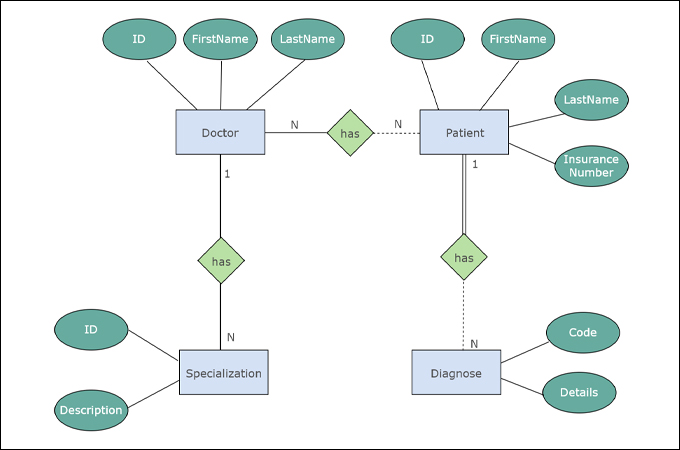
Elements of ERD:
→ Entity: Represents a real-world object or concept, such as a person, place, or event. It is depicted as a rectangle.
→ Attribute: Represents properties or characteristics of an entity. It is depicted as an oval connected to its entity.
→ Relationship: Represents how entities are related to each other. It is depicted as a diamond connected to related entities.
→ Primary Key: A unique identifier for an entity. It is usually underlined within the entity rectangle.
→ Foreign Key: An attribute that creates a link between two entities. It is used to establish relationships between entities.
Process Steps for Creating an ERD:
→ Step 1: Identify the entities that will be represented in the ERD. These entities typically correspond to tables in the database.
→ Step 2: Identify the attributes of each entity. These attributes will become the columns of the corresponding tables.
→ Step 3: Determine the relationships between entities. Identify how entities are related to each other and the nature of their relationships.
→ Step 4: Draw the entities as rectangles and their attributes as ovals. Connect the attributes to their respective entities.
→ Step 5: Draw the relationships as diamonds and connect them to the related entities. Label the relationships to describe their nature.
Structure Chart
A Structure Chart is a diagram that represents the hierarchical structure of a system, showing how various components or modules interact with each other. It is used primarily in software engineering to illustrate the breakdown of a system into smaller, manageable parts.
Example Structure Chart:

Elements of Structure Chart:
→ Module: Represents a distinct part of the system that performs a specific function. It is depicted as a rectangle.
→ Control Module: A special type of module that coordinates the actions of other modules. It is depicted as a rectangle with a line at the bottom.
→ Library Module: Represents reusable code or functions. It is depicted as a rectangle with a double line at the bottom.
→ Data Couple: Represents data passing between modules. It is depicted as an arrow labeled with the data being passed.
→ Control Couple: Represents control information passing between modules. It is depicted as a dashed arrow.
Process Steps for Creating a Structure Chart:
→ Step 1: Identify the main module of the system, which will be at the top of the chart. This module represents the overall system or major function.
→ Step 2: Break down the main module into sub-modules that perform specific tasks. These sub-modules should represent smaller, more specific functions.
→ Step 3: Continue breaking down sub-modules into smaller modules until each module represents a single, well-defined task.
→ Step 4: Identify the data and control couples between modules. Show how data and control information flow between the modules.
→ Step 5: Draw the structure chart, starting with the main module at the top. Place sub-modules below their parent modules and connect them with lines. Use arrows to represent data and control couples.
Data Dictionary
A Data Dictionary is the repository of information about data items such as the origin of data, data structure, data usage, and other metadata information related to data elements. It is used as a system of record for structure charts and other references. Data dictionaries help organize and document the information related to data flows, data processes, and data elements in a structured fashion.
Benefits of Data Dictionaries:
→ Provides a highly structured definition and details of data elements.
→ Identifies all aliases and reduces duplicates within data elements.
→ Helps in developing logic for processes.
→ Assists in the construction and validation of DFDs and structure charts.
→ Aids in the development of reports.
Contents of Data Dictionary:
→ Data Element/Item Details: Information about individual data elements, including unique ID, name, aliases, default value, length, description, data type, input format, output format, comments, and validation criteria.
→ Data Structure and Definition: Describes complex data elements using symbols such as "composed" (equals), "and" (+), "or" (|), "optional" (0), and "repetition" ().
→ Data Process Details: Information related to data processes, including process name, inputs, outputs, type, and logic executed in the process.
→ Data Stores: Specifies the storage format of data elements, such as flat files or database records, including volume and frequency of data storage, file system details (file name, path, restrictions), and database storage information (table, schema name).
Data Element/Item Details:
→ Unique Id: Uniquely identifies the data element. Example: StudentId.
→ Name: Specifies the name of the data element. Example: StudentFirstName.
→ Alias: Known aliases for the data element. Example: Pupil, ProgramMember, CollegeStudent.
→ Default Value: The value stored if no value is specified. Example: "Indian" for "Citizenship" attribute.
→ Length: Minimum and maximum length of the data element.
→ Description: A description of the data element.
→ Data Type: Specifies the data type of the element, such as integer, real number, string.
→ Input Format: The format for inputting the data element.
→ Output Format: The format for outputting the data element.
→ Comments: Additional comments about the data element.
→ Validation Criteria: Validation requirements for the data element, such as data type validation or range validation.
Developing a Data Dictionary:
→ Step 1: Identify the main data elements, data stores, data processes, and external and internal entities.
→ Step 2: Describe the data structure and element details for the identified data elements.
→ Step 3: Expand all data flows and data stores to describe the data structure of their data elements.
Example: For instance, a "book record" for a library can be described as follows:
Book Record = Book ID + Book Name + Author Name + Publisher Name + (Publication Date)