BCS041 - Fundamentals of Computer Networks Revision Notes
Hey there! Welcome to KnowledgeKnot! Don't forget to share this with your friends and revisit often. Your support motivates us to create more content in the future. Thanks for being awesome!
Computer Networks allows autonomous digital devices to communicate to each other for various purpose using either wired or wireless connection.
- Goals of Computer Networks - Facilitating Communication, Resource Sharing, Data Storage and Access, Cost Effieciency, Reliability and Redundancy
- Application of Computer Networks - Business and Commerce, Education, Healthcare, Government, Scientific Research, Travel and Hospitality.
- Criteria - Delivery & Accuracy, Performance, Reliability, Security, Scalability
Data Communication are the exchange of data between two devices via some transmission medium. It has five components - Message, Sender, Receiver, Transmission medium, Protocol.
Transmission Mode refers to the method by which data is transmitted between devices.
- Simplex Mode- One direction communication. (Ex- Tv Broadcast, Radio Broadcast, Alarm System)
- Half-Duplex Mode- Bidirectional communication but not simultaneosly (Ex- Walkie Talkie)
- Full-Duplex Mode- Both side communication at same time (Ex- Telephone, Internet)
Type of connections in computer networks
→ Point to Point provides dedicated link between two devices. (Ex- Telephone)
→ Multipoint more that two devices share a single link
Difference between Analog Communication and Digital Communication
| Analog Communication | Uses analog signal for transmission, Signals represented by sine waves, Signals consist of continuous value, Affected by noise, High probability or error, Requires complicated hardware, Cheaper than digital comm. Need low Bandwidth Requires high power Less portable, Low quality data transmission, Not very precise, Ex- Sound shows analog sign |
| Digital Communiction | Uses digital signals, Signal represented by square waves, Signal consists of discrete values, Not affected by noise, Immune to parallax errors, Require less complicated hardware, Costly in nature Need high bandwidh, Require less power Poratble, High quality data transmission, Very precise, Ex- Computer uses digital signals |
Difference between Synchronous Transmission and Asynchronous Tranmission
| Synchronous Transmission | Data is sent in form of block, Fast and costly, Time interval of transmission is constant, User have to wait till the transmission is complete, No gap between data, Efficient use of transmission lines, The start and stop bits are not used, Need precisely synchronized clock, Error are detected and corrected in real time, Low latency, Example - Telephonic conversation, Online gaming. |
| Asynchronous Transmission | Data is sent in the form of bytes, Slow and Economical, Time interval of transmission is random, User do not have to wait for the completion of transmission, There is gap between data, Transmission line remains empty, The start and stop bits are used, Does not need synchronized clock, Error are detected and corrected when the data is received. High latency, Example - Email, File transfer, Online forms |
Difference between Serial Transmission and Parallel Transmission
| Serial Transmission | Single communication link is used, data(bit) flow bidirectional, Cost efficient and Simple Circuit, One bit is tranfferd at one clock pulse, Comparable slower, Used for long distance, Full Duplex, Reliable and Straightforward |
| Parallel Transmission | Multiple parallel links is used, Data flow multiple lines, Not cost efficient and complex circuit, Eight bits is transffered at one clock pulse, Comparable Fast, Used for short distance, Half Duplex, Unreliable and complicated |
ISO - OSI Model - International Starndard Organisation - Open Systems Interconnection
The modern Internet is not based on OSI, but on the simpler TCP/IP model. However, the OSI 7-layer model is still widely used, as it helps visualize and communicate how networks operate, and helps isolate and troubleshoot networking problems.
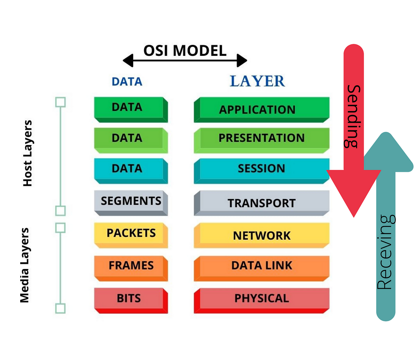
| # | Layer | Definition | Services | Sending Behavior | Receiving Behavior |
| 1 | Physical Layer | Responsible for the physical connection between devices, handling the transmission and reception of raw bit streams over a physical medium. | Bit Transmission
Physical Topologies
Data Encoding
Hardware Specifications
Signal Transmission and Reception
Modulation | Converts digital data from the Data Link Layer into electrical, optical, or radio signals.
Transmits these signals over the physical medium (cables, wireless). | Receives incoming signals from the physical medium.
Converts these signals back into digital data for the Data Link Layer. |
| 2 | Data Link Layer | Ensures reliable node-to-node data transfer and handles error correction from the physical layer. | Framing
Physical Addressing
Error Detection and Correction
Flow Control
Access Control | Packages data into frames.
Adds MAC addresses and error-checking information.
Sends frames to the Physical Layer. | Receives frames from the Physical Layer.
Checks frames for errors and corrects them if possible.
Extracts data from frames and forwards it to the Network Layer. |
| 3 | Network Layer | Manages the delivery of packets from the source to the destination across multiple networks. | Logical Addressing
Routing
Packet Forwarding
Fragmentation and Reassembly
Error Handling and Diagnostics | Determines the best path for data packets.
Adds logical (IP) addresses to packets.
Routes packets to the Transport Layer. | Receives packets from the Data Link Layer.
Removes logical addresses.
Reassembles fragmented packets.
Forwards packets to the Transport Layer. |
| 4 | Transport Layer | Ensures complete data transfer with reliable and sequential packet delivery between end systems. | Segmentation and Reassembly
Connection Establishment and Termination
Error Detection and Recovery
Flow Control
Multiplexing | Splits messages into segments.
Adds sequence numbers and error-checking information.
Sends segments to the Network Layer. | Receives segments from the Network Layer.
Checks for errors and retransmits if necessary.
Reassembles segments into messages.
Forwards messages to the Session Layer. |
| 5 | Session Layer | Manages and controls the dialog between two computers. | Session Establishment, Maintenance, and Termination
Dialog Control
Synchronization
Session Recovery | Establishes, manages, and terminates sessions.
Synchronizes data exchange.
Sends data to the Transport Layer. | Receives data from the Transport Layer.
Maintains and synchronizes sessions.
Forwards data to the Presentation Layer. |
| 6 | Presentation Layer | Translates data between the application layer and the network format. | Data Translation
Data Encryption and Decryption
Data Compression
Data Serialization | Translates data into network formats.
Encrypts and compresses data.
Sends formatted data to the Session Layer. | Receives formatted data from the Session Layer.
Decrypts and decompresses data.
Translates data into application formats.
Forwards data to the Application Layer. |
| 7 | Application Layer | Provides network services directly to user applications. | Network Process to Application
Resource Sharing and Device Redirection
Directory Services
Authentication
User Interface
Network Management | Initiates data transfer from user applications.
Sends data to the Presentation Layer for formatting. | Receives data from the Presentation Layer.
Provides data to user applications.
Facilitates user interaction with the network. |
Encapsulation - The process of wrapping data packets with header information as they move through different network layers. This header contains details like source and destination addresses, allowing routers and switches to forward the packet to the correct destination.
Decapsulation - reverse process, where the receiving network device strips away the headers from the data packet to access the original information. This allows the device to interpret and process the data appropriately based on its destination and content.
End-to-end Agreement - It is a mutual understanding or contract between the sender and receiver of data packets regarding how communication should be handled. This agreement ensures that the data transmission meets certain requirements or specifications, such as reliability, security, or quality of service. It typically involves protocols and mechanisms implemented at both ends of the communication path to ensure that data is transmitted, received, and processed correctly according to the agreed-upon terms.
Protocol design issues involve addressing various aspects to ensure effective communication between networked devices. Key issues to consider for designing protocols include:
Data format: Define how data is structured, encoded, and formatted for transmission and interpretation by both sender and receiver.Address format: Specify how addresses are assigned and represented to identify the source and destination of data packets.Address mapping: Determine mechanisms for translating logical addresses (e.g., IP addresses) to physical addresses (e.g., MAC addresses) for routing purposes.Routing: Establish algorithms and protocols for determining the optimal paths for data packets to travel through the network.Acknowledgment scheme: Define methods for acknowledging receipt of data packets to ensure reliable delivery and detect transmission errors.Data loss and damage: Implement mechanisms for detecting and recovering from packet loss or corruption during transmission.Sequence control: Manage the order in which data packets are sent and received to ensure proper reconstruction of the transmitted information.Flow control: Regulate the rate of data transmission between sender and receiver to prevent congestion and optimize network performance.Singal Modulation is the process of varying one or more properties of a carrier signal—such as its amplitude, frequency, or phase—to encode information from a message signal for transmission over a communication channel
Need or Benefits for Signal Modulation
- Efficient Transmission: Enables long-distance communication by converting low-frequency signals into higher frequencies.
- Multiplexing: Allows multiple signals to share the same channel without interference.
- Noise Reduction: Improves signal quality and resilience against noise and interference.
- Antenna Size: Reduces the required size of transmitting and receiving antennas.
- Bandwidth Utilization: Optimizes the use of available bandwidth for transmitting more data.
Types of Signal Modulation
Analog Modulation : Modulation where the carrier signal is varied in a continuous manner in proportion to the message signal.
- Amplitude Modulation (AM):Varies the amplitude of the carrier signal.Use: AM radio broadcasting.
- Frequency Modulation (FM):Varies the frequency of the carrier signal.Use: FM radio broadcasting, audio signals.
- Phase Modulation (PM):Varies the phase of the carrier signal.Use: Digital synthesizers, some communication systems.
Digital Modulation:
- Amplitude Shift Keying (ASK):Varies the amplitude of the carrier signal to represent digital data.Use: Optical fiber communications, RFID systems.
- Frequency Shift Keying (FSK):Varies the frequency of the carrier signal to represent digital data.Use: Modems, low-frequency communication.
- Phase Shift Keying (PSK):Varies the phase of the carrier signal to represent digital data.Use: Wi-Fi, satellite communication.
- Quadrature Amplitude Modulation (QAM):Combines ASK and PSK to modulate both amplitude and phase.Use: Cable television, broadband internet.
- Orthogonal Frequency Division Multiplexing (OFDM):Encodes digital data on multiple carrier frequencies.Use: 4G/5G mobile communication, digital television.
Multiplexing
Multiplexing combines multiple data streams into a single transmission medium for efficient resource use. It allows several users or devices to share a channel simultaneously without interference. Key techniques include:
| Technique | Definition | Advantages | Disadvantages |
| Time Division Multiplexing (TDM) | Divides channel into fixed time slots for data transmission. Each user gets a dedicated time slot. | Simple implementation, Efficient for bursty data, Flexible allocation of slots | Inefficient for continuous data, Requires synchronization, Less efficient bandwidth use |
| Frequency Division Multiplexing (FDM) | Divides channel into frequency bands for simultaneous data transmission. Each user occupies a separate frequency band. | High data rate support, Efficient for continuous data, No synchronization needed | Susceptible to interference, Fixed bandwidth allocation, Requires guard bands |
| Code Division Multiplexing (CDM) | Assigns unique codes to users for simultaneous data transmission. Users share the same frequency spectrum using orthogonal codes. | High security, Dynamic bandwidth allocation, Robust against interference | Complex encoding/decoding, Increased processing overhead, Performance degrades with high traffic |
| Space Division Multiplexing (SDM) | Divides physical space into separate channels. Each user gets exclusive use of a portion of the transmission medium. | No interference between users, High data rates, Simple implementation | Requires additional physical infrastructure, Limited scalability, Vulnerable to physical damage or environmental factors |
Switching
Switching is a fundamental concept in networking and telecommunications, enabling the routing of data between multiple devices or networks. It involves directing data from its source to its destination through intermediate nodes or switches.
Types of Switching:
| Types | Packet Switching | Message Switching | Circuit Switching |
| Definition | Divides data into packets; each packet independently routed | Entire messages stored and forwarded from node to node | Establishes dedicated communication path before transmission |
| Working | Packets forwarded based on destination address; flexible routing | Messages held at nodes until path to destination available, then forwarded as a whole | Physical circuit reserved for communication duration |
| Example | Internet Protocol (IP) networks (e.g., internet) | Traditional postal mail system | Traditional telephone networks |
| Advantages | Efficient use of resources, adaptable routing, resilient to network failures | Simple implementation, suitable for low-volume traffic, no real-time requirements | Predictable latency, guaranteed bandwidth, suitable for real-time applications |
| Disadvantages | Variable latency, potential packet loss, overhead from packet headers | High latency, inefficient resource use, message storage requirement | Inefficient for bursty traffic, high setup time, idle period wastage |
Transmission Medium
Transmission medium refers to the physical pathway through which data travels from one device to another. It can be classified into guided and unguided transmission media.
Guided Transmission Media: Use physical paths to transmit data signals. Common types include: Twisted Pair Cable, Coaxial Cable
Unguided Transmission Media: Transmit data through air or space without a physical pathway. Common types include: Radiowave, Micowave, Infrared
| Transmission Medium | Definition | Working | Examples | Advantages | Disadvantages | Image Representation |
| Twisted Pair Cable (UTP and STP) | Consists of twisted copper wires; UTP lacks shielding, while STP has additional shielding | Signals transmitted through twisted pairs; STP provides better protection against interference | Telephone lines, Ethernet connections | UTP: Affordable, easy to install; STP: Better protection against electromagnetic interference | UTP: Susceptible to interference; STP: More expensive | 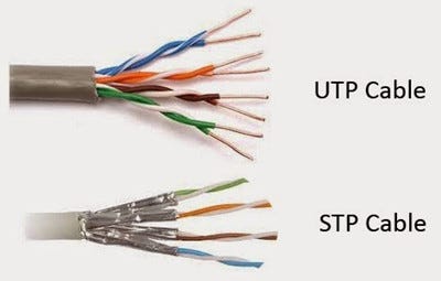 |
| Coaxial Cable | Central copper conductor surrounded by insulating material and a metallic shield | Signals transmitted through the central conductor; shield provides protection against interference | Cable television networks, high-speed internet connections | High bandwidth, less susceptible to interference | Costlier than twisted pair cables | 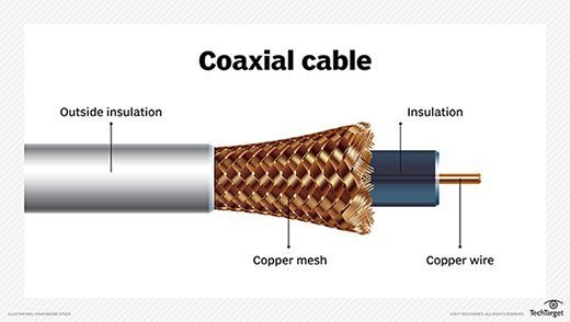 |
| Optical Fiber | Transmits data using light pulses through a glass or plastic fiber | Signals transmitted as light pulses through fiber; immune to electromagnetic interference | Long-distance telecommunications, high-speed internet connections | High bandwidth, low attenuation, immune to electromagnetic interference | Expensive to install and maintain | 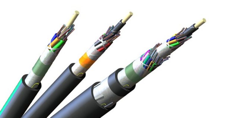 |
| Wireless Transmission (Radio Waves) | Utilizes electromagnetic waves to transmit data wirelessly | Signals transmitted as radio waves through the air | Wi-Fi, Bluetooth, cellular networks | Offers mobility, flexibility | Signal interference, limited range | Can't be seen through eyes |
| Microwave Transmission | Uses high-frequency radio waves for long-distance transmission | Signals transmitted as high-frequency radio waves between antennas | Long-distance telephone networks, cellular backhaul connections | High data rates, long-distance transmission | Requires line-of-sight, vulnerable to weather conditions |
| Infrared Transmission | Utilizes infrared light waves for short-range wireless communication | Signals transmitted as infrared light waves between devices | Remote controls, proximity sensors, short-range data transfer | Secure communication, immunity to radio interference | Requires line-of-sight, limited range |
Connectors
The connectors are the interface for communication between computers/ computers to hub, switch, router etc. In LAN basically used connector are discussed as follows:
| Type & Image | Details |
RJ45
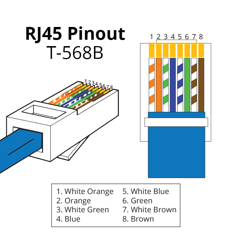 | Standard Ethernet connector for networking computers in LANs. Commonly used in both residential and commercial networks. Supports speeds up to 10 Gbps over twisted-pair cables. Easy to install and widely available, but limited to 100 meters without signal boosters. |
RJ11
 | Telephone line connector for connecting phones and modems. Typically used for DSL internet connections and traditional telephony. Simple and cost-effective, but lower data transmission rates compared to RJ45. Supports up to 4 wires, primarily used in residential telephone networks. |
BNC
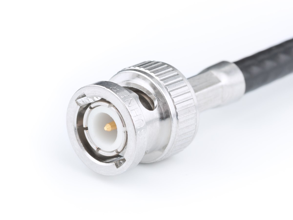 | Quick connect/disconnect for video signals, RF, and networking. Commonly used in television production, amateur radio, and network testing equipment. Secure connection with good shielding, but bulky and not suitable for very high-frequency applications. Requires proper alignment for optimal performance. |
F-Type
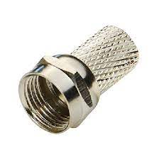 | Screw-on connector for cable TV, satellite TV, and broadband. Provides a strong, reliable connection. Commonly found in residential setups for connecting TV and internet services. Requires proper installation to avoid signal loss and ensure optimal performance. Suitable for frequencies up to 1 GHz. |
SC
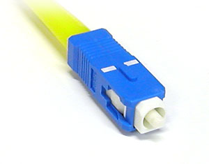 | Push-pull connector for data centers and telecom networks. Used in fiber optic networks for its easy connect/disconnect feature. High performance with low signal loss, but bulkier than other connectors. Commonly used in high-speed internet and cable TV networks. Known for its square-shaped design. |
ST
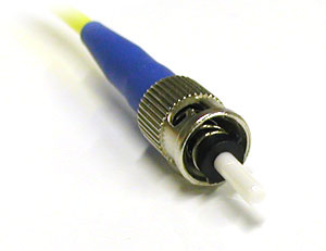 | Bayonet-style fiber optic connector for data communication. Reliable and easy to use, but bulkier and not suitable for high-density applications. Commonly used in long-distance networks and networking environments where quick connection and disconnection are required. Features a twist-on mechanism for secure connection. |
LC
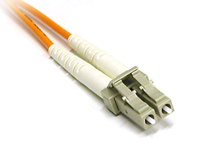 | Smaller push-pull connector for high-density fiber optic networks. Compact and high performance, making it ideal for densely packed data centers. More fragile than larger connectors but offers superior performance in space-constrained environments. Common in modern high-speed networks and telecommunications. |
SMA
 | Coaxial RF connector for antennas and Wi-Fi devices. Reliable with good performance at higher frequencies. Commonly used in wireless communication devices, including Wi-Fi equipment and RF amplifiers. Requires precise installation for optimal performance, supporting frequencies up to 18 GHz. |
U.FL
 | Miniature coaxial RF connector for laptops, GPS, and Wi-Fi cards. Compact and suitable for tight spaces. Fragile and limited to lower power applications, but essential in devices where space is at a premium. Common in modern electronics requiring compact RF connections. |
Classification of Networks
LAN, or Local Area Network, is a network that connects computers and devices within a limited geographical area, such as a building or campus. It typically employs Ethernet or Wi-Fi technology for data transmission and is commonly used in homes, offices, and schools.
MAN, or Metropolitan Area Network, spans a larger area than a LAN but is smaller than a WAN. It covers a city or a large campus, connecting multiple LANs together. MANs often use fiber optic cables or wireless technologies and are found in urban environments, facilitating communication within a metropolitan area.
WAN, or Wide Area Network, transcends geographical boundaries to connect multiple LANs and MANs over a broad area, such as a country or continent. It includes the Internet and multinational company networks, utilizing various technologies like leased lines, satellites, or submarine cables to facilitate long-distance communication.
Network Topology refer to the way in which a network is laid out physically or the geometric representation of the relationship of all the links and linking devices to one another.
Types of Topologies
| Name | Identification | Advantages | Disadvantages |
| Mesh | Every device has a dedicated point-to-point link. Needs n(n-1) duplex links. | No traffic problem, Robust, Privacy or security, Easy fault identification. | Installation and reconnection are difficult, Bulk wiring, Expensive. |
| Star | Each device has a point-to-point link only to a central controller or hub. | Less expensive than mesh, Easy to install and reconfigure, Robust, Easy fault identification and isolation. | Dependency on single point (the hub), More cabling. |
| Bus | Every computer and network device is connected to a single backbone cable. | Need only 1 backbone cable, Less costly, Coaxial or twisted pair cable is used. | Backbone fails then system crashes, Heavy traffic, Low security, High collision chance. |
| Ring | Ring connecting devices with exactly two neighboring devices. | High-speed transmission, Minimum collision, Cheap, Costly than star. | Single node fails then system crashes, Difficult troubleshooting, Less secure. |
| Tree | Variation of the star topology with hierarchical flow of data. | Easy error detection and error correction. | Central hub fails then system crashes, Difficult reconfiguration. |
| Hybrid | Combination of various topologies. | Very flexible, Easy to add new devices. | Hard to design the architecture, Expensive hub, Requires bulk cabling. |
MAC(Media Access Contorl)
it refers to the set of protocols and mechanisms used to control access to a shared communication medium in a network. The MAC layer is responsible for managing how devices on the network access and transmit data over the physical medium, such as Ethernet cables or wireless radio frequencies.
Media Access Control (MAC) is essential in networking for several reasons:
- Efficient Resource Utilization: MAC protocols help optimize the use of network resources, ensuring that multiple devices can share the same communication medium effectively.
- Collision Avoidance: In shared network environments, such as Ethernet LANs, MAC protocols prevent collisions by regulating when devices can transmit data, thereby maximizing network efficiency.
- Fairness: MAC protocols aim to provide fair access to the network for all devices, ensuring that no single device monopolizes the network resources, which is crucial for maintaining network performance and user satisfaction.
- Priority Handling: Some MAC protocols support prioritization mechanisms, allowing certain types of traffic to be transmitted with higher priority than others. This is essential for applications that require low latency or guaranteed quality of service (QoS).
- Error Detection and Correction: MAC protocols often incorporate error detection mechanisms to identify and correct transmission errors, ensuring data integrity and reliability.
- Security: MAC protocols can also contribute to network security by implementing access control mechanisms to prevent unauthorized devices from accessing the network.
MAC Techniques
MAC techniques are methods used to control how data packets are transmitted between multiple devices over a shared communication channel. The primary categories include:
- Random Access - Aloha(Pure, Slotted), CSMA
- Round Robin - Polling, Token Passing
- Reservation - Centralized, Decentralized
| Technique | Definition | Advantage | Disadvantage | Uses/Example |
| Pure Aloha | Devices can transmit whenever they have data. If a collision occurs, they wait a random time before retransmitting. | Simple implementation | High collision rate | Early wireless communication systems |
| Slotted Aloha | Time is divided into slots. Devices can only transmit at the beginning of a time slot. | Lower collision probability than Pure Aloha | Requires time synchronization | Satellite communication |
| CSMA | Devices sense the channel before transmitting. If the channel is busy, they wait until it is free. | Reduces collisions compared to Aloha | Still susceptible to collisions | Ethernet networks |
| CSMA/CD | Devices listen while transmitting to detect collisions. If a collision is detected, they stop and wait before retransmitting. | Efficient for wired networks | Not suitable for wireless networks | Wired Ethernet LANs |
| CSMA/CA | Devices attempt to avoid collisions by using strategies like waiting for a random backoff time before attempting to retransmit. | Reduces collisions in wireless networks | Overhead due to collision avoidance mechanisms | Wi-Fi networks |
| Polling | A central controller polls each device in turn to grant permission to transmit. | Ensures fair access | Central point of failure | Centralized network systems |
| Token Passing | A token circulates in the network. Only the device holding the token can transmit. | Eliminates collisions | Token loss or corruption can disrupt communication | Token ring networks |
| Centralized Reservation | A central controller manages the reservation and allocation of resources. | Efficient and organized resource allocation | Central point of failure | Time-division multiplexing (TDM) systems |
| Distributed Reservation | Devices coordinate among themselves to manage reservations and resource allocation. | No central point of failure | Complex coordination mechanisms | Distributed wireless networks |
TCP/IP Protocol
The TCP/IP model, also known as the Internet Protocol Suite, is a set of communication protocols used to interconnect network devices on the internet. It is divided into four abstraction layers, each serving specific functions to ensure the smooth transfer of data from one device to another.
Application Layer
- Web Browsing: Facilitates accessing and interacting with web content through browsers.
- File Transfer: Enables the upload and download of files over a network.
- Email Services: Supports sending, receiving, and storing email messages.
- Domain Name Resolution: Translates human-readable domain names into IP addresses.
- Remote Login and Management: Allows users to access and control remote computers securely.
- Network File Services: Provides access to files over a network as if they were on local storage.
Transport Layer
- Reliable Data Transfer: Ensures data is delivered accurately and in the correct sequence, providing acknowledgment and retransmission mechanisms.
- Unreliable Data Transfer: Sends data without ensuring delivery or order, suitable for applications needing speed over reliability.
- Flow Control: Manages the rate of data transmission to prevent network congestion and ensure efficient communication.
- Error Detection and Recovery: Detects errors in transmitted data and initiates retransmissions if necessary to ensure data integrity.
- Segmentation and Reassembly of Data: Breaks large messages into smaller segments for transmission and reassembles them at the destination.
Internet Layer
- Logical Addressing: Assigns IP addresses to devices, allowing them to be uniquely identified on the network.
- Routing and Forwarding of Packets: Determines the best path for data packets to travel across networks and forwards them to their destination.
- Error Reporting: Provides feedback about network issues, such as unreachable hosts or networks, to help diagnose problems.
- Network Diagnostics: Helps diagnose network problems using tools like ping and traceroute to identify connectivity issues.
- Address Resolution: Maps IP addresses to physical MAC addresses for local network communication, ensuring proper data delivery.
- Multicast Management: Handles the delivery of data to multiple recipients simultaneously, optimizing network resource usage.
Link Layer (Network Access Layer)
- Physical Addressing: Uses MAC addresses to identify devices on a local network segment, enabling local communication.
- Access to Physical Transmission Medium: Controls how data is placed onto and taken off the physical medium, such as Ethernet cables or wireless signals.
- Data Framing: Encapsulates network layer data into frames for transmission and processes received frames to extract the data.
- Error Detection on Physical Medium: Identifies errors that occur at the physical layer and discards corrupted frames to maintain data integrity.
- Flow Control over the Physical Medium: Manages the rate of data transmission between devices, ensuring smooth and efficient communication.
- Encapsulation of Network Layer Data: Wraps network layer packets into frames for transmission over the physical medium, ensuring proper data handling.
| Protocol Name | Full Form | Layer Name | Use | Port Number(s) | Additional Details |
| HTTP | HyperText Transfer Protocol | Application | Web browsing | 80 | Stateless protocol, uses TCP, primarily for fetching web pages. |
| HTTPS | HyperText Transfer Protocol Secure | Application | Secure web browsing | 443 | Encrypts data for secure transmission, uses SSL/TLS. |
| FTP | File Transfer Protocol | Application | File transfer | 20, 21 | Uses separate control and data connections. |
| SMTP | Simple Mail Transfer Protocol | Application | Email sending | 25 | Transfers emails between mail servers. |
| POP3 | Post Office Protocol version 3 | Application | Email retrieval | 110 | Downloads emails from server to client, then deletes from server. |
| IMAP | Internet Message Access Protocol | Application | Email retrieval and storage | 143 | Allows multiple clients to manage the same mailbox. |
| DNS | Domain Name System | Application | Translating domain names to IP addresses | 53 | Critical for internet functionality, resolves hostnames. |
| DHCP | Dynamic Host Configuration Protocol | Application | Dynamic IP address assignment | 67, 68 | Automates IP configuration for devices on a network. |
| Telnet | Teletype Network | Application | Remote command-line access | 23 | Unencrypted, replaced by SSH for secure communications. |
| SSH | Secure Shell | Application | Secure remote command-line access | 22 | Encrypts data, replacing Telnet for secure access. |
| LDAP | Lightweight Directory Access Protocol | Application | Directory services | 389 | Accessing and maintaining distributed directory information services. |
| SNMP | Simple Network Management Protocol | Application | Network management | 161 | Collecting and organizing information about managed devices on IP networks. |
| RDP | Remote Desktop Protocol | Application | Remote desktop access | 3389 | Allows users to connect to another computer over a network connection. |
| TFTP | Trivial File Transfer Protocol | Application | Simple file transfer | 69 | Basic file transfer protocol without authentication, uses UDP. |
| TCP | Transmission Control Protocol | Transport | Reliable, connection-oriented communication | Variable | Ensures data delivery through error-checking and retransmission. |
| UDP | User Datagram Protocol | Transport | Fast, connectionless communication | Variable | Used for applications where speed is critical, e.g., DNS, streaming. |
| IP | Internet Protocol | Internet | Logical addressing and packet routing | N/A | Defines addressing and routing for packets across networks. |
| IPv4 | Internet Protocol version 4 | Internet | Logical addressing and routing | N/A | Uses 32-bit addresses, supports up to 4.3 billion addresses. |
| IPv6 | Internet Protocol version 6 | Internet | Logical addressing and routing | N/A | Uses 128-bit addresses, supports a vastly larger number of devices. |
| ICMP | Internet Control Message Protocol | Internet | Error reporting and diagnostics | N/A | Used by network devices to send error messages and operational information. |
| IGMP | Internet Group Management Protocol | Internet | Manages multicast group memberships | N/A | Used for streaming media and other multicast applications. |
| ARP | Address Resolution Protocol | Internet | Mapping IP addresses to MAC addresses | N/A | Essential for local network communication, translates IP to hardware addresses. |
| NAT | Network Address Translation | Internet | Translates private IP addresses to public IP addresses | N/A | Enables multiple devices on a local network to share a single public IP address. |
| Ethernet | N/A | Link | Local area network (LAN) communication | N/A | Defines wiring and signaling for LANs, standardized as IEEE 802.3. |
| Wi-Fi | Wireless Fidelity | Link | Wireless network communication | N/A | Defines wireless LAN communication, standardized as IEEE 802.11. |
| PPP | Point-to-Point Protocol | Link | Direct communication between two nodes | N/A | Used in dial-up connections. |
| SLIP | Serial Line Internet Protocol | Link | Encapsulates IP packets for transmission over serial connections | N/A | An older protocol largely replaced by PPP. |
| LLDP | Link Layer Discovery Protocol | Link | Network device discovery | N/A | Allows network devices to advertise information about themselves. |
Error detection is a method used in communication systems to identify errors that may occur during the transmission of data over a network. This ensures the integrity of the transmitted data. Below are some commonly used error detection methods along with their steps:
Parity Bit Method
The parity bit method adds a single bit to the data to make the number of 1's either even (even parity) or odd (odd parity).
Steps for Parity Bit Method:
- Choose parity type (even/odd).
- Calculate parity bit based on the number of 1's:
- For even parity, if the count is odd, set the parity bit to 1; if even, set it to 0.
- For odd parity, if the count is even, set the parity bit to 1; if odd, set it to 0.
- Append parity bit to data.
- Transmit data with parity bit.
- Receiver checks parity:
- Even parity: Count of 1's should be even.
- Odd parity: Count of 1's should be odd.
Cyclic Redundancy Check (CRC)
CRC is a more robust error detection method that uses polynomial division to detect changes in raw data.
Steps for CRC:
- Choose a generator polynomial.
- Append zeros to data.
- Perform binary division using the generator polynomial.
- Append CRC remainder to data.
- Transmit data with CRC.
- Receiver performs division:
- If remainder is zero, data is correct.
- If remainder is non-zero, an error is detected.